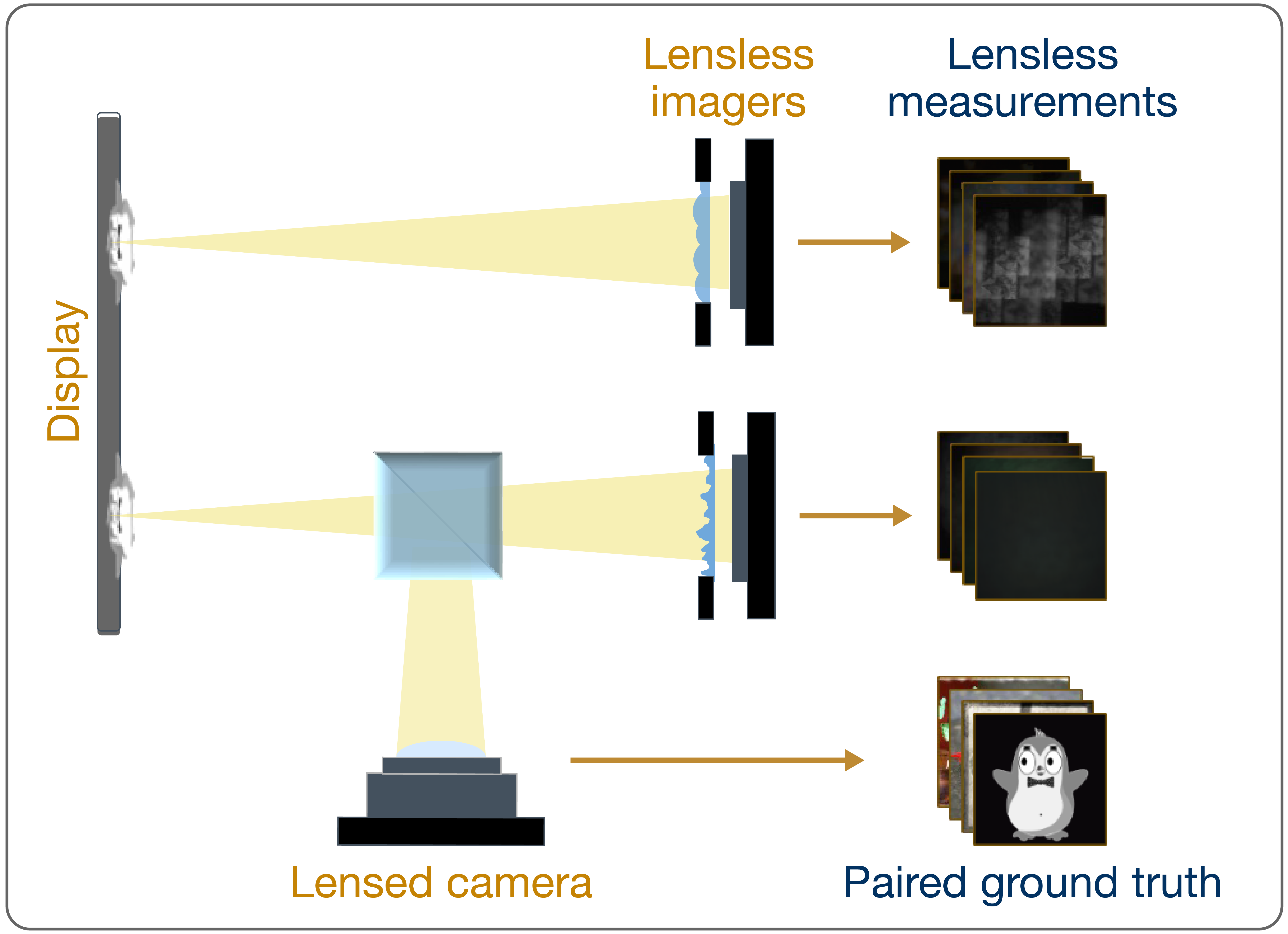
Building the system
We chose to build our system on an optical breadboard so it can be portable for in-the-wild captures. We used a breadboard that was readily available in our lab, which set size constraints of our system. All sensors are connected to power through the Basler USB Hub.
1. Mount the ground truth camera
First, we mounted an f=6 mm lens to our board level sensors using an S-mount. Then, we mounted the camera onto a right-handed kinematic mount. We added double-sided tape to the clamps of the mount to minimize wiggling.
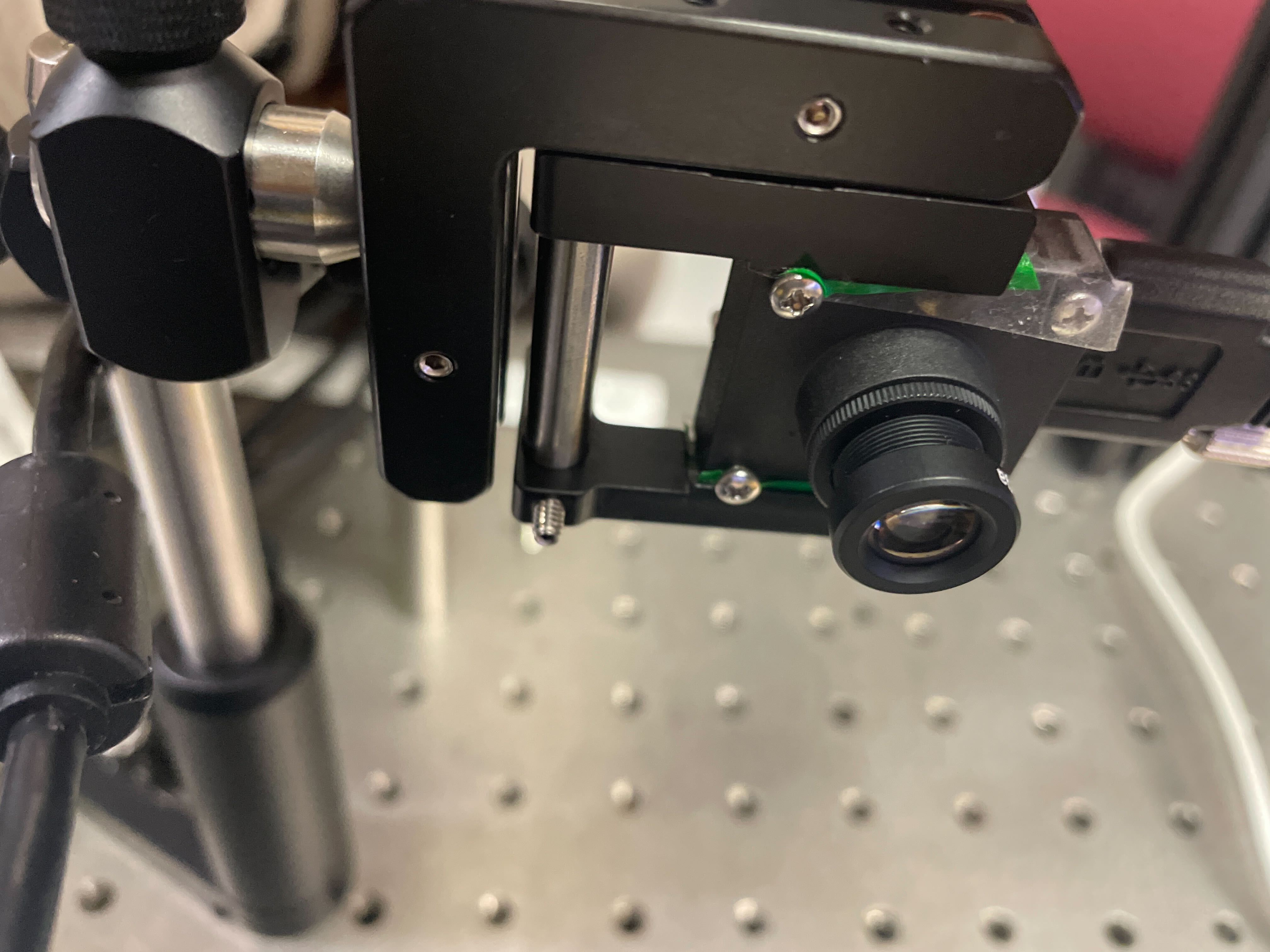
Taping the lensed camera
Back view of mounted lensed camera
2. Build the lensless imagers
For both the RML and Diffuser, we first mounted the board level sensors onto a 2-to-1 baseplate. Because the Basler board level sensors we used were not compatible with our existing baseplates, we 3D printed a custom 2-to-1 mount that allowed us to attach our lensless imagers to an off-the-shelf Thorlabs plate. This would allow us to attach the Thorlabs plate to an optical post.
To build the Diffuser, we taped a piece of diffuser (large enough to cover the sensor) onto the mounted board level by putting double-sided tape on its screws, roughly 4.5mm from the sensor. We also added padding using layers of tape. We created a small aperture using black masking tape by shining a point source at the imaging distance and created an aperture to limit the PSF extent to the center of the sensor. More details can be found here.
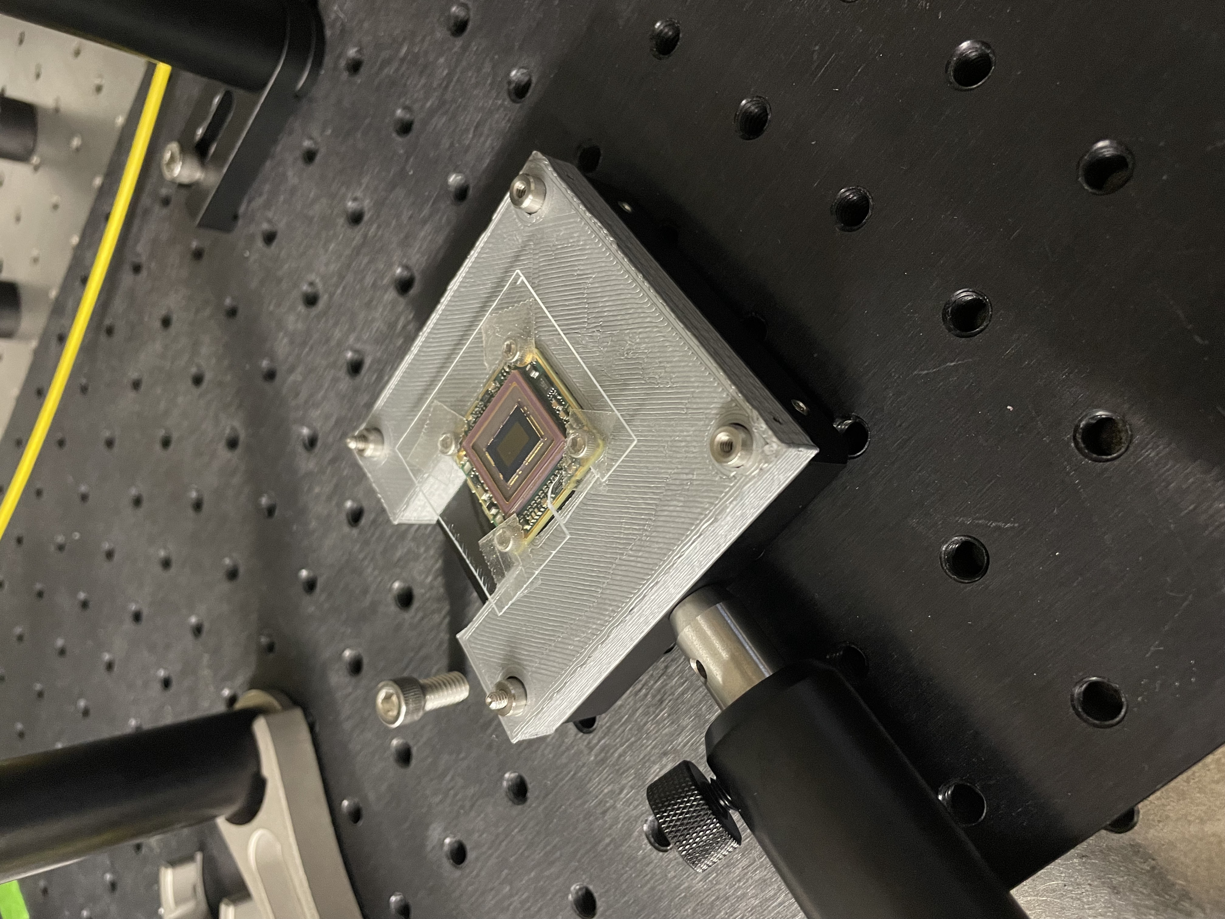
Board level sensor mounted on a custom 3D printed mount and Thorlabs baseplate
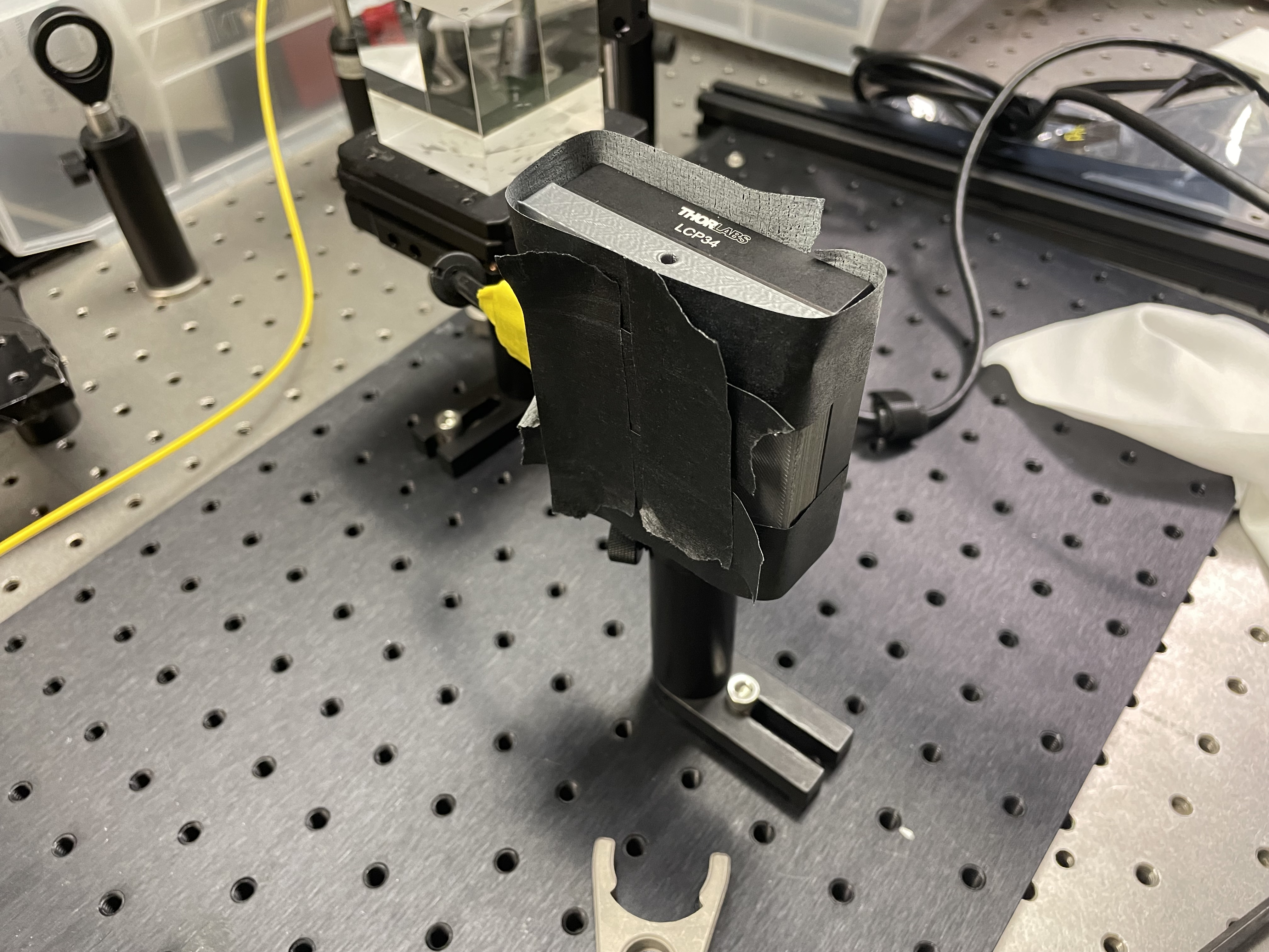
Our mounted Diffuser
Aligning the beamsplitter, lensed camera, and Diffuser
To build the RML imager, we mounted a custom phase mask onto an optical post. Using black masking tape and black cardboard, we built a small enclosure around the mounted board level sensor to block stray light. This phase mask has a longer sensor-to-mask distance, so placing the board level sensor and RML on two separate posts makes alignment easier.
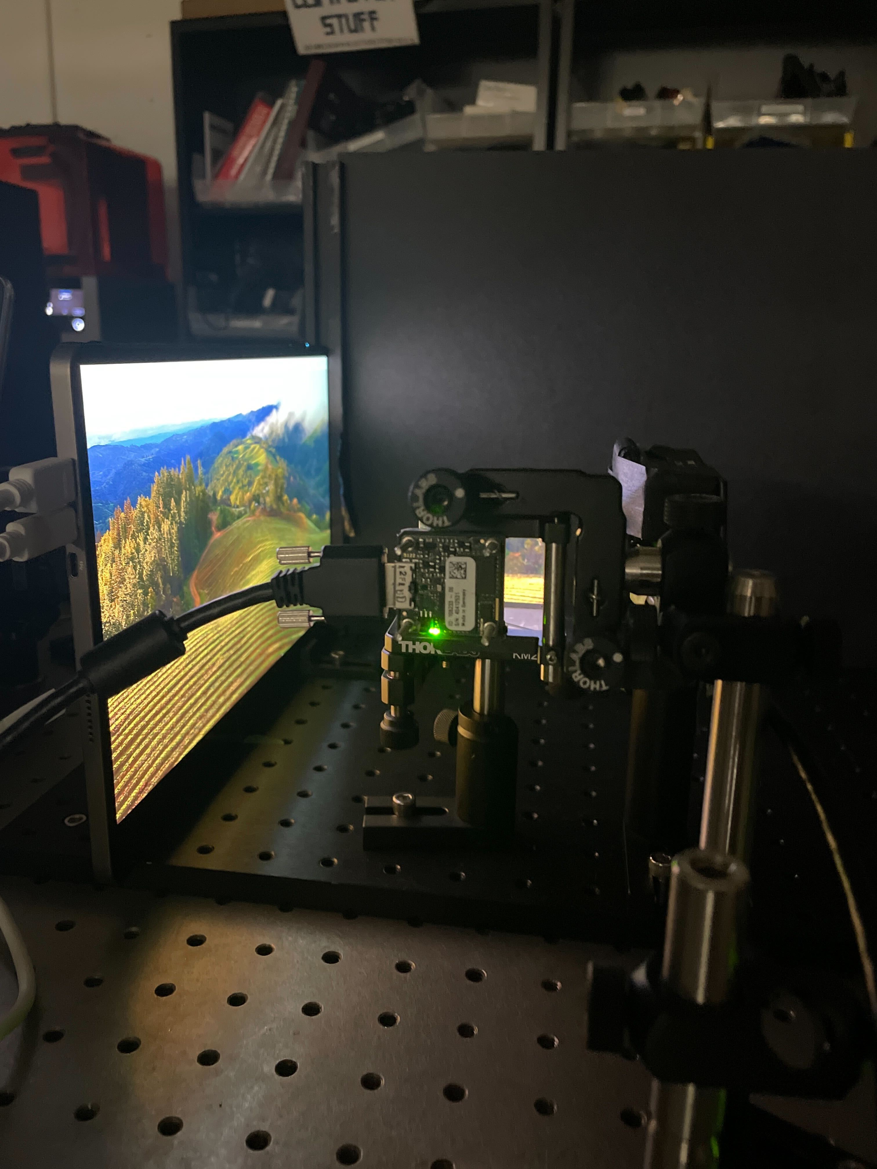
3. Place components on breadboard
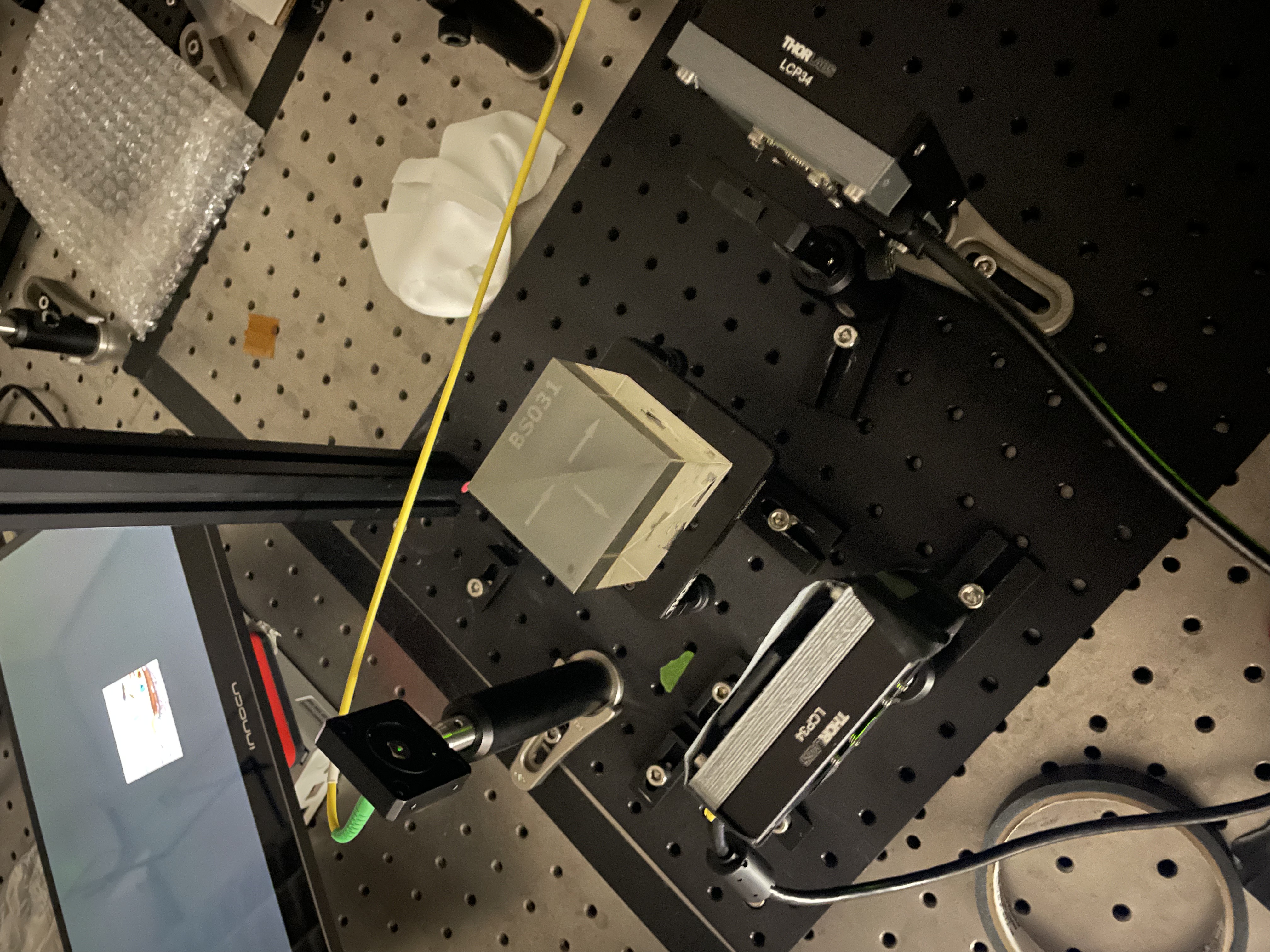
First, we placed our display screen at the edge of the breadboard. We decided to place our display screen horizontally to maximize the size of the images we could display. We secured the display using clamps on both sides which allowed us to easily remove the display by loosening the clamps. We divided the display in half with a black separator, leaving one side for the RML and the other for the Diffuser and lensed camera. We chose to split the Diffuser with the beamsplitter due to higher light throughput of the Gaussian diffuser. Then, we placed the beamsplitter ~12cm away from the display screen. We aligned the lensed camera and Diffuser to the beamsplitter using a point source (30mm and 25mm from the edge of the beamsplitter to sensor, respectively).
On the other side, we placed the mounted board level for the RML ~150mm from the display screen. To it, we aligned the RML phase mask 18mm from the sensor. The RML and Diffuser are 135mm apart horizontally, parallel to the display.
Calibrating the RML using a point source
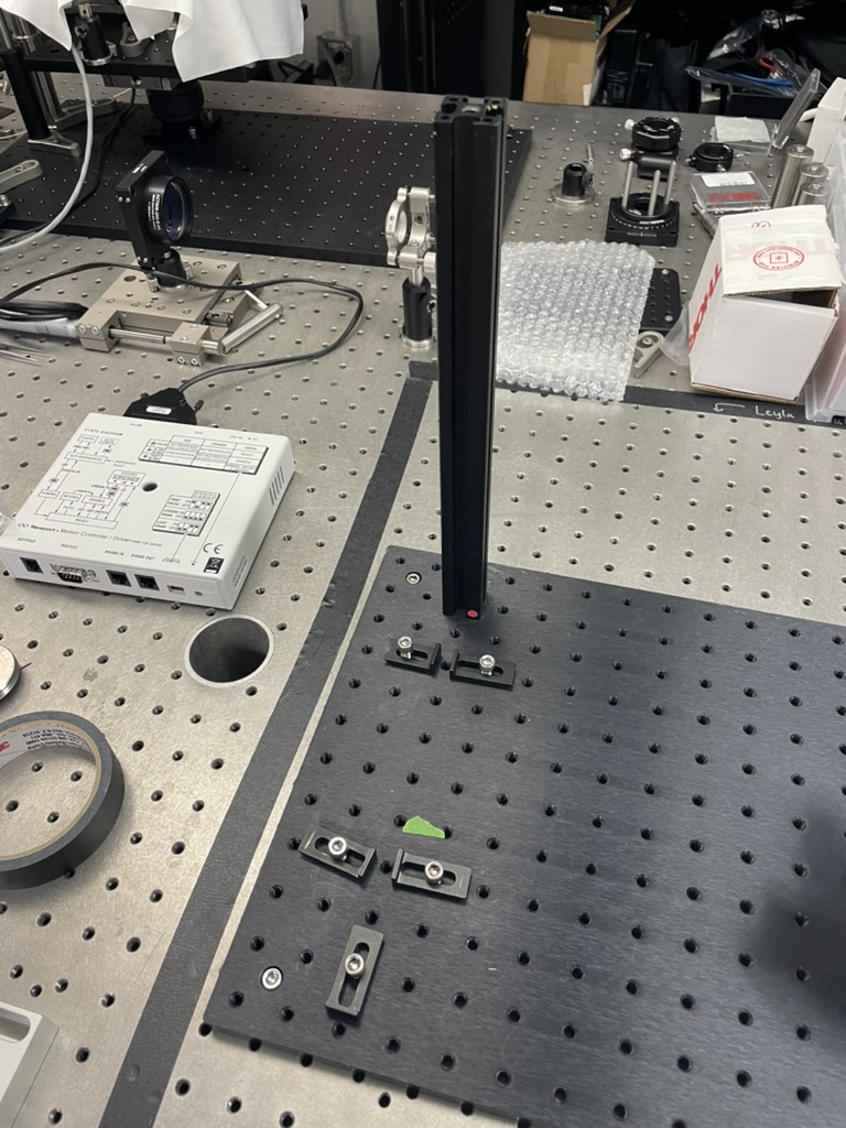
Clamps installed to secure the display
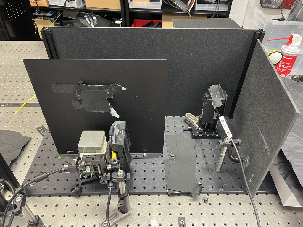
Diffuser, lensed camera, and RML on the breadboard
4. Aligning and calibrating the imagers
After placing components on the breadboard and coarsely aligning them, we optically aligned the imagers (which includes making sure the sensors are on-axis with the display screen) and acquired calibration PSFs.
For the lensed camera, we displayed a test image and adjusted the focus ring until it was in focus with the surface of the screen. For the RML and Diffuser, we placed a point source at the same depth as the display. Then, we adjusted the height of the point source such that the PSF was vertically centered on the sensor. Lastly, we adjusted the tilt of the point source such that it would produce the brightest PSF, which meant the point source is on-axis with the phase mask.
5. Correct for stray light
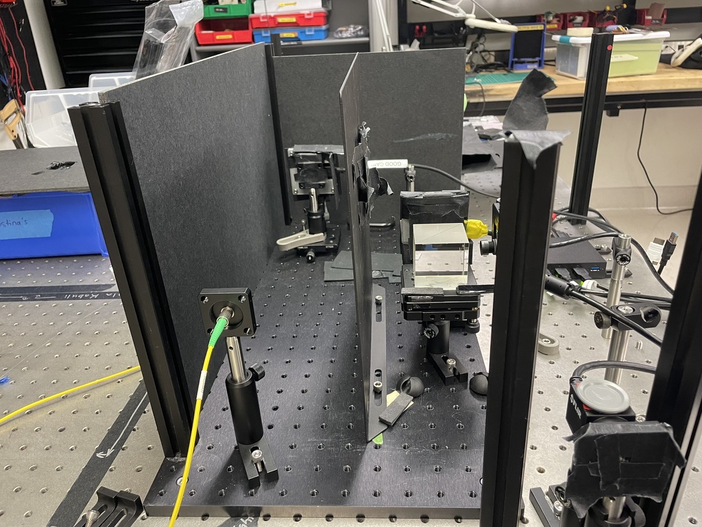
Before capturing data, we corrected for stray light as much as possible. We built an enclosure around the system using black cardboard and matte black foil to block ambient light. We added dividers between the display and the beamsplitter to prevent the lensed camera and Diffuser from capturing light directly from the display instead of through the beamsplitter. We also built small enclosures around the lensless sensors to prevent the sensors from capturing ambient light.
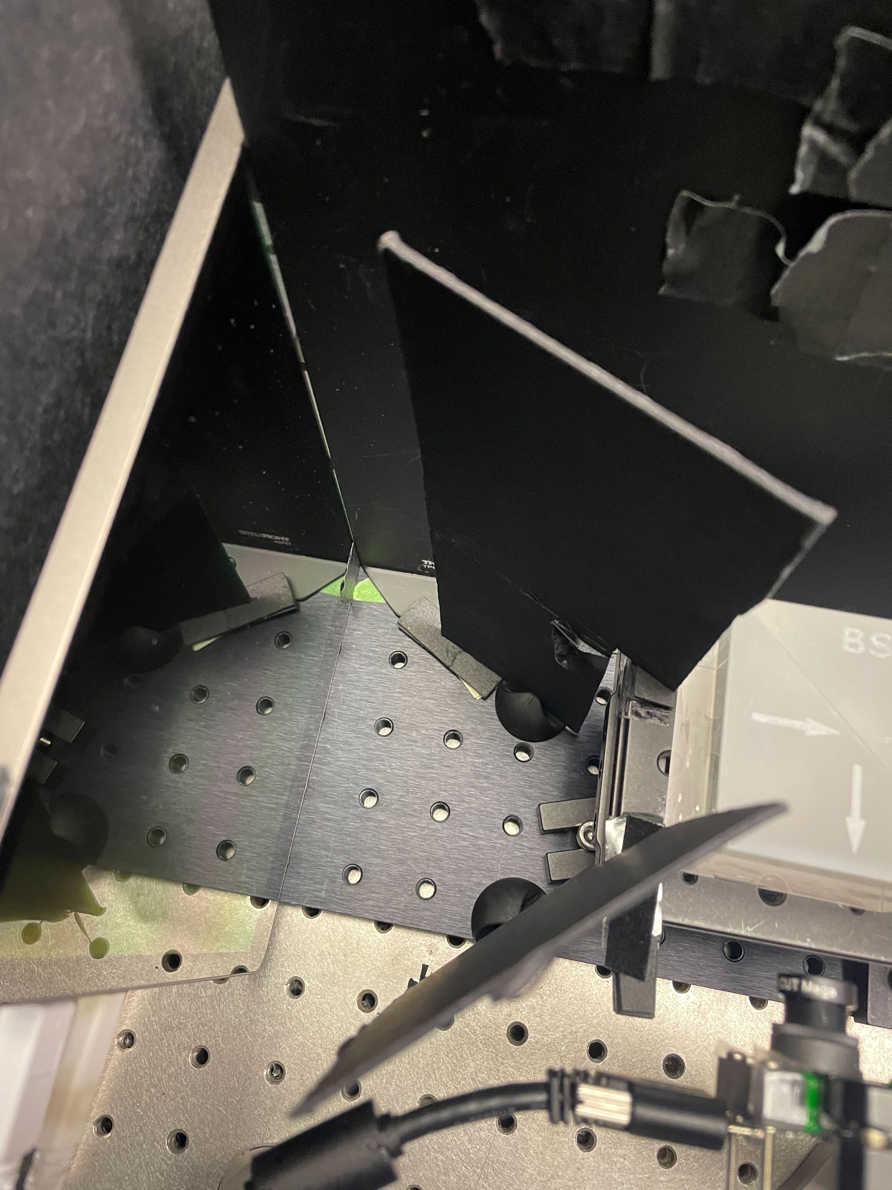
Dividers between display and beamsplitter to control for stray light.
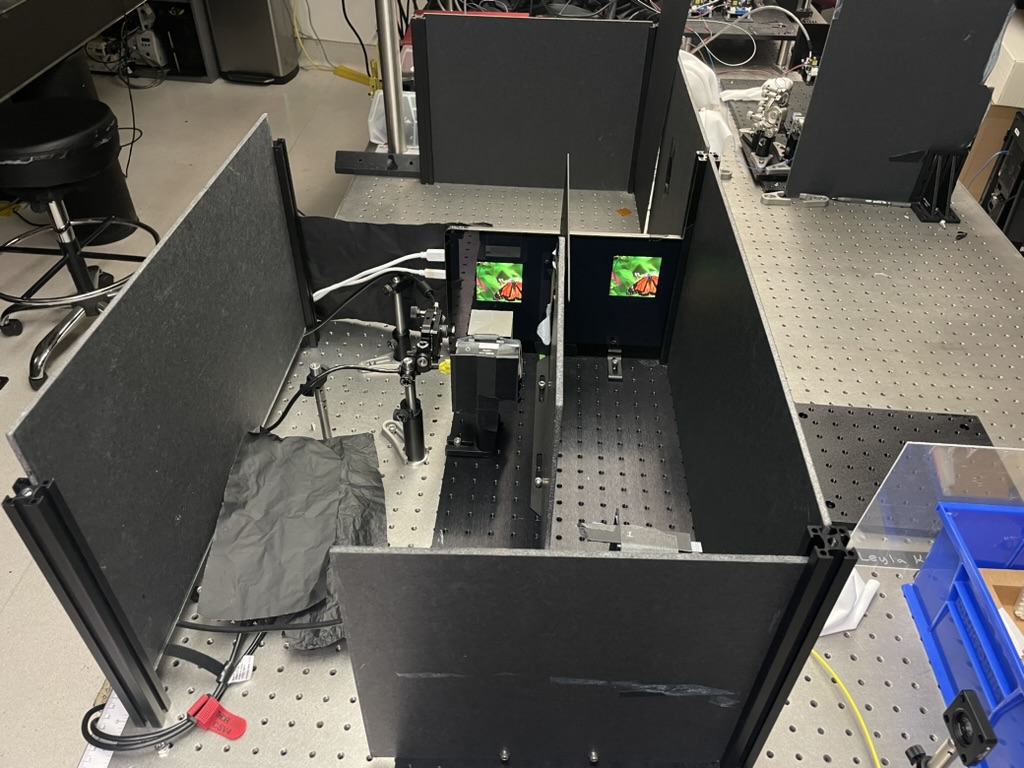
Full hardware set up with images being displayed.